Direct Answer
Bubbles are pockets of gas trapped in glass. Some remain after melting and refining, and others can be trapped during a hot forming step. A seed is a small bubble. To decide whether a bubble is acceptable in a lamp shade, cover or lens, verify its location, whether it opens to a surface, and how it appears in the fixture under the agreed conditions. Apply the drawing, specification or approved reference for that zone.
Describe the feature before assigning a cause
A small bright point in a clear cover can look dark when the viewing angle changes. Start with what can be located and repeated. Record which face is toward the light source, where the point sits relative to the rim, and which lighting reveals it. If the feature appears to lie in the glass wall, record that observation and retain an orientation view so the same point can be found again after the part has been moved.
A bubble contains gas. Glassmakers use seed for a very small bubble and can intentionally introduce gas pockets as decoration. Terms such as blister are used differently across glass product specifications. If a drawing or purchase specification uses one of these labels, confirm the definition used on that project. The term alone gives little information about the location, shape or disposition of the feature. Corning Museum of Glass glass dictionary
An enclosed bubble remains within the wall. A surface-breaking bubble has an opening at a face or edge and deserves a separate entry because the surface condition may affect how the part seats, seals or cleans. A reflection, a solid inclusion and a surface pit can resemble a bubble from one angle. Use the agreed lighting and look again at the same position from a second view. If depth or identity remains uncertain, retain the part for the specified follow-up check. See the guide to locating other lighting glass defects for the wider inspection workflow.
On a curved cover, a photograph can show the near face, the far face and a reflection of the source at once. Use an orientation photograph of the whole part before taking the close view. Note which side was illuminated and which side was viewed. If the close view is used to report size, follow the agreed scale or calibration method so the recorded dimension has a reproducible meaning.
How gas becomes trapped in glass
Gas generated during melting
When a glass batch is heated, some raw materials release gases as they react and decompose. Bubbles in the melt can grow, rise and leave at the surface during fining, also called refining in this context. The rate of removal depends on the bubble size, the viscosity of the melt, the time available and the behavior of the gases in that glass. Smaller bubbles can persist when their rise is slow or the conditions for reabsorption are insufficient. Lehigh University course notes on glass melting and fining
An enclosed seed in a finished shade can therefore be investigated as a possible carryover from the hot glass used to make it. Compare parts from the same glass supply that took different routes through the forming and finishing operations. A similar pattern across several shapes makes the shared material history worth reviewing. Record the lot evidence before assigning the defect to a furnace, a particular charge or an operator.
Fining conditions are chosen for the glass composition and its process. Changes in temperature can affect both melt viscosity and gas exchange with the bubble, so the bubble population can change as the melt heats or cools. A discussion about process correction should begin with the relevant glass lot and thermal history. Review how the proposed change would be evaluated on the finished parts as well as in the melt. Glass bubble rise during heating and cooling cycles
Gas trapped during hot forming
Hot forming creates another opportunity for gas to be enclosed. In one documented example, small pockets were retained when a flaw in an optical glass preform was closed during reheat pressing. That observation is specific to the material and route in the example. For another glass part, compare the repeat position with its own forming sequence and with samples from before and after the operation. A local cluster or elongated pocket can guide the investigation. Part history is needed to distinguish competing causes. SCHOTT TIE-28 on bubbles and inclusions in optical glass
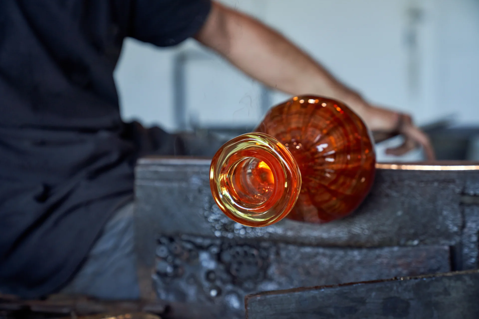
In mold blowing, the air used to expand the hot glass body occupies the hollow interior. The glass wall surrounds that cavity. An enclosed bubble is a pocket within the wall, so its location should be described separately from the cavity that forms the shade. When talking to a custom hand blown glass shade manufacturer, show the defect relative to the opening and any tool or fixture reference. That orientation makes it possible to compare parts without guessing which surface the inspector saw.
The Easter Glass video below shows hand mold blowing as a forming operation. Watch how the hollow form is shaped inside a mold, then relate the outer wall and open interior to a section drawing of the part under review. The footage provides forming context. The origin or acceptance of a particular bubble is established from the affected part and its records.
| Possible origin or observation | What the feature can look like | Useful comparison |
|---|---|---|
| Carryover from melt | Enclosed seeds that recur across parts from shared glass supply. | Compare different shapes or tools made with traceable glass lots. |
| Hot forming | A localized pocket or group in a region repeatedly affected by the same operation. | Compare matching locations and any samples taken before and after the operation. |
| Unresolved surface feature | A bright point that appears to open at a face or edge. | Locate the opening using the agreed method, then review surface and fit requirements. |
Why the same bubble can matter in one zone and pass in another
Clear covers and shades
Look at the part in the finished assembly and separate the exposed field from the rim or neck. A clear cover over a compact source can reveal a point more strongly in the illuminated state than on a diffuse inspection bench. A part with a masked perimeter may hide the point at normal viewing distance. Define those regions on the drawing or reference photograph and use the installed orientation when comparing the appearance of two samples.
The clear oval borosilicate lighting cover is a practical geometry example. Its shallow dome and perimeter rim give the review team two regions to describe separately. Inspect a point in the exposed dome as a visible feature. At the rim, record whether an opening intersects the mating face or whether the observed feature is enclosed. The borosilicate glass cover and shade range includes clear and textured forms for which this distinction is useful.
Optics and diffusers
A gas pocket creates an interface inside the glass. Light can be redirected at that interface. The resulting change depends on where the pocket sits relative to the useful beam, its apparent size, and the source and optical geometry. A bench image helps locate and compare the feature. An agreed fixture check shows whether it causes a visible point, streak or change in the required output under that assembly’s conditions. Use a defined optical test where the part specification calls for one. SCHOTT TIE-28, optical application discussion
A shallow domed optical glass lens makes this distinction concrete. Its drawing can separate the useful aperture from the locating or seating region. A bubble inside the useful aperture is evaluated for its optical or appearance effect, using the agreed test. A surface opening near the rim is evaluated against the relevant interface requirement. The optical glass lens and diffuser collection illustrates why an intended transmitting face needs its own acceptance conditions.
In a fixture with more than one emitter, a feature may be visible when the closest emitter is energized and less visible when the whole array is on. Use the operating state agreed for approval and keep the sample in the intended holder. A useful light check records what the observer sees or what the specified instrument measures, with the source settings and observation geometry attached. This lets later reviews compare results across samples with the same setup.
For lit appearance approval for optical glass diffusers, place the sample over the specified emitter and keep the standoff, orientation and observation position consistent. Review the area under the conditions defined for the product. Share both the orientation view and the close view with the glass diffuser supplier, especially if several points appear as one bright patch when the assembly is lit. That record separates a count in the glass from the appearance of the illuminated fixture.
Decorative bubbles
A clear bubble glass tube with a mounting neck illustrates a different design intent. Visible bubbles are part of the described appearance of that product. The project can agree the character of the decorative field with a reference sample and define separate requirements at the neck or other functional areas. Review the distribution, grouping and appearance of the bubble pattern under the agreed light. Evaluate any opening or edge condition against the requirement for the surface where it occurs.
What to agree before sample approval
Define the inspection and the acceptance basis
For bubble acceptance criteria for blown glass shades, start with the drawing zones and their function. Identify the clear viewing field, the intended decorative area and the mounting interface. Agree how an individual point and a group will be recorded, which part of an open feature is measured and whether the lighted assembly is checked. The reference sample should be tied to the same drawing revision and viewing setup as the written criteria.
| Item | What to record | Why it matters |
|---|---|---|
| Zone and location | Usable aperture, exposed wall, decorative field or seating region. | Ties the observation to the function of the zone. |
| Feature description | Enclosed or open, apparent size, count and grouping. | Allows repeat comparison under the chosen method. |
| Viewing conditions | Source, orientation, background and position. Specify fixture state if used. | Supports consistent visibility and lit appearance decisions. |
| Decision basis | Drawing revision, specification, sample or functional test. | Gives the reviewer an agreed criterion for disposition. |
Where an optical project uses the ISO 10110 drawing system, Part 18 covers how tolerances for bubbles and inclusions and other internal material imperfections are indicated. ISO 12123 addresses raw optical glass. Technical documents for some raw optical glasses report aggregate bubble and inclusion cross-sectional area relative to an examined volume. The units, inclusion rules and interpretation follow the applicable document. A finished decorative shade or cover can use its own agreed zone, size, count, grouping and appearance criteria. ISO 10110-18 and ISO 12123
Consider how the inspection record will handle a group. A rule based on the largest individual bubble answers a different question from one based on how many points are visible in a defined area. For a decorative sample, the visual density of the group can matter as much as any single point. Put the measurement convention and the treatment of groups in the agreement. If a zone is defined on the drawing, identify how its boundary is transferred to the part before deciding which observations belong to it.
An approved sample can represent the intended appearance. A limit sample can illustrate the boundary for a defined feature under the agreed view. Label each with the part revision, region and conditions it represents. If the lighting design changes, confirm whether the same reference still represents what will be visible. Easter Glass describes using drawings, reference samples and agreed scope in its lighting component inspection process.
If the decorative reference and the written drawing appear to give different outcomes, identify the exact feature in dispute. Ask the project team to confirm which requirement controls the appearance and which controls fit or optical function. Record that decision with the drawing revision, reference sample ID and approval date. A retained reference becomes easier to apply when its purpose and viewing conditions travel with it to the production or inspection team.
Make the observation repeatable
Use a clean sample, fix its orientation, and note the source position and background. Record the face or zone, the apparent extent by the agreed method, the count or distribution, and whether the feature appears enclosed or open. Attach the annotated view to the record. Choose an agreed way to handle touching features and clusters so a second inspector can reproduce how they were counted.
During OEM drawing review for custom glass covers, give the borosilicate glass cover supplier both a drawing view and a section through the seating area. For made-to-drawing lamp shades, add the installed orientation and the reference for the cosmetic field. For custom diffuser sample approval, include the specified light source and fixture setup. These inputs let the engineering team tie each observation to one criterion and separate a request for more evidence from a decision to accept or segregate the part.
Worked example with two marks on one light cover
Suppose a clear cover has a small enclosed bubble on its face and a shallow open feature near the rim. On the bench both can appear as bright points. Mark their positions on the same orientation view. Inspect the face in the installed light path using the agreed sample or test, and record how the point looks at the stated viewing position. For the rim, confirm whether the opening reaches the contact area and check that area against the drawing and the assembly requirement.
The first observation may be acceptable under the visual reference while the second calls for further review of the rim condition. If the part is examined before the sample criterion is agreed, record the observations and ask for the missing decision basis. The drawing and sample approval should identify who reviews a borderline case and what evidence they need. The example illustrates a decision sequence. Each project sets the actual limits and disposition.
At a subsequent review, suppose the emitter is moved closer to the cover. Keep the same marked samples and compare the former and revised assemblies using the approved viewing position. If the change makes the face point more prominent, revisit the lit appearance agreement for that zone. If the mounting interface also changes, recheck the rim under its revised fit requirement. Keeping the two results separate helps the team decide which design change affected the approval.
Review a recurrence with the production team
When multiple parts show a similar feature, compare the pattern by lot, shape and position relative to the tool or fixture. A recurring point at a fixed position may justify looking for a common operation at that location. A distribution across several shapes may justify reviewing shared glass supply. Include any samples that locate when the feature first appears. The comparison is most useful when the feature descriptions and inspection conditions are consistent.
If an investigation identifies a likely stage, agree how the next samples will verify the proposed correction. Compare the same zone under the same inspection conditions and review the relevant function in the assembly. Keep the observed result, the cause hypothesis and the approval decision in separate fields. A revision to a process or an appearance limit should be traceable to the evidence and approval for that revision.
Technical Takeaway
Describe a suspected bubble by location, distribution and surface condition before assigning it a cause. Review shared glass supply and forming history when the feature recurs. Decide acceptance by the agreed criteria for the actual part zone, including the illuminated fixture where appearance or optical function depends on it. Keep a photo or sample reference with the recorded method so someone else can repeat the check.
Frequently Asked Questions
Why are there small bubbles in a blown glass shade?
Small gas pockets can remain from the glass melt or be retained during a later hot forming step. Compare their position and distribution across parts from the same material lot and process to narrow the investigation.
Can glass be specified with no visible bubbles?
A project can set a visual requirement for the specified zones and conditions. The agreement should state the viewing method, the scope of the check and how a borderline feature is recorded. A defined inspection result describes what was detected under those conditions.
How should bubbles be counted?
Use the method in the drawing or inspection agreement. A finished cover may use size, count, zone and grouping, while an optical raw-glass specification may use a defined area-based report. Record the method and the observed region with the result.
Who decides whether a bubble is acceptable?
Use the acceptance basis approved for the project by the responsible parties. Start with the specified zone, condition and reference sample or test, then send any unresolved feature through the agreed review process.
Review the bubble criteria for your lighting component
Share the drawing revision, a marked view of the affected area and the agreed inspection conditions. Include the reference sample or fixture setup if the feature changes when lit. Those records help define the observation, test and approval needed for the next sample.
Share the drawing and bubble observation
Technical note
The four diagrams and the worked example are illustrative. Use the material, geometry, inspection method and acceptance criteria documented for your own component.
 English