Direct Answer
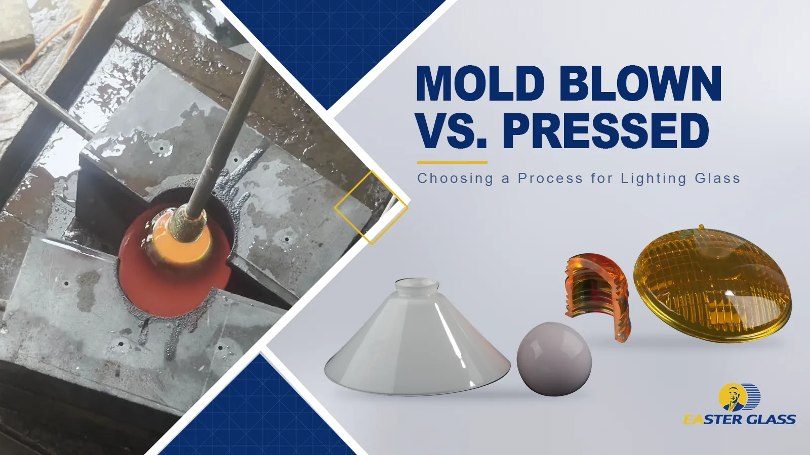
Start with mold blowing when the essential feature is a hollow shell, such as a globe around a light source, and the outside contour is the main shape to reproduce. Start with mold pressing when the job depends on forming specific faces, such as a stepped lens surface and a seating rim, that a mold and plunger can shape. When the geometry could suit either route, compare how each would form the critical surfaces, release the part, finish the opening or rim, and produce a sample that fits the fixture and meets its appearance or light-distribution requirement.
What does each forming route control?
Imagine two glass domes of the same outside diameter. One encloses an LED module and needs a neck that fits a retaining ring. The other sits directly over an emitter and uses a shaped face to redirect light. A silhouette drawing makes the two parts look similar. A section drawing reveals different design jobs. For the first dome, the space inside the shell, the opening and the wall around the neck drive the discussion. For the second, the relative positions of the shaped face, the seating surface and the light source carry more weight. The comparison starts there because the two forming routes establish the surfaces in different ways.
Mold blowing shapes the outside of a hollow shell
In mold blowing, air expands a hot glass preform against a cavity. The cavity can establish the exterior profile and carry an exterior pattern. The inner surface develops as the glass expands and redistributes. Two parts can therefore follow the same outside profile while differing in wall thickness at a shoulder or near the opening. For a lighting component, show both the outside envelope and the internal clearance the fixture needs, then define where wall thickness matters. The wider subject of glassblowing includes other ways to shape an inflated body. This comparison uses the Corning Museum of Glass definition of mold blowing.
Mold pressing shapes glass between a mold and a plunger
In conventional mold pressing, the plunger pushes hot glass into the space bounded by the tooling. The opposing tool faces can define different contours, such as a stepped face on one side of a shallow part and a smoother profile on the other. The location and shape of each face matter because they determine which tool feature forms it and how that feature clears the glass during release. A shallow recess, rim or relief can be part of the design if the tools can form and release it. See the Corning Museum of Glass entry on pressed glass.
A process description sometimes uses both verbs. In container manufacture, press-and-blow can use a plunger to shape the preliminary body before air expands it in a final mold. For the lighting comparison, the relevant distinction is which action forms the surface that matters on the finished component. A container preform process and a plunger-formed lighting lens answer different design questions. The equipment supplier Eurotherm describes this sequence for bottles and jars in its container glass forming guide.
Compare the requirements before choosing a route
Read the following table across each row and mark the features that would cause the fixture to fail an assembly or optical check. If a globe needs space for a light engine and its wide shoulder is mostly decorative, the interface at the narrow opening can carry the tightest functional requirement. If a shallow disc sets the beam, the relationship between its optical face and seating rim may govern the decision. Keep features that are important only to appearance in a separate list. This lets the engineering team concentrate the first feasibility review on the few surfaces that control the outcome. For other forming and finishing routes, see the lighting-glass forming overview.
| Decision point | Mold blowing | Mold pressing | What to verify |
|---|---|---|---|
| Geometry | Hollow shell with an outside shape set by the cavity. | Tool-accessible inner and outer faces, including shallow shells. | Section through opening, widest area and seating interface. |
| Wall thickness | Thickness can vary along a molded exterior profile. | Tool spacing defines intended thickness where both faces are formed. | Local readings at critical locations on a finished sample. |
| Surface | Cavity can transfer a pattern to the shell exterior. | Tool faces can form a relief or an opposing profile. | Viewing conditions for appearance and a defined profile for functional relief. |
| Mounting | Opening and edge condition may depend on later finishing. | A tool can form a rim. Review any subsequent finish on the contact face. | Finished part in the actual holder or a representative interface. |
| Tool release | Review the tool split and where its joint may show on the shell. | Review plunger withdrawal and any feature that could trap the tool. | Tool movement through a section showing the most constrained geometry. |
| Light | A shade can be evaluated for appearance and source clearance in the fixture. | An optic can be evaluated against its intended light distribution. | Installed source, orientation and the agreed acceptance method. |
Start with the hollow envelope and the mounting interface
Consider a decorative pendant with a rounded globe shade with a short mounting neck. The holder engages the neck. The drawing needs to show how the holder enters the globe, where the glass seats and which surfaces must clear the light engine. The body diameter may describe the visible shape, while the inside diameter of the mouth and the position of the seating face determine whether the globe goes onto the fixture. For a made-to-drawing glass shade, dimension the assembled condition as well as the glass. A fixture section can expose interference where a connector enters at an angle or where the shoulder narrows around a module that clears the widest part of the globe.
Wall thickness deserves its own set of review locations. Specify where to check it, such as at a neck transition, on the shoulder or at the part of the body nearest the light engine. Pick locations according to the fixture function and agree how they can be reached and measured. A neck reading gives a measurement at the neck. A minimum clearance check answers whether the light engine can pass through the opening and stay clear in service. In one container-forming study, the initial temperature distribution of the preform affected predictions of finished wall thickness in the blow-blow process. See the Eindhoven University of Technology research record.
The opening also needs an agreed inspection condition. For example, ask the blown glass shade manufacturer to review the final opening after any specified trimming or edge finishing. If a ring bears on an annular face, identify that face and the area the ring may contact. A fit check should use the specified ring or a representative fixture interface with the same seating and retention geometry. When a sample catches at the opening, record where the contact occurs and compare the mouth, the edge and the mating hardware. That observation gives the team a specific feature to revise before it changes the outline or the forming route.
Decide whether a texture is decorative or optical
The same word can describe different requirements. A ribbed shade may need a visually continuous pattern around a curved shell. A ribbed or prismatic lens may need defined facets that steer light when the component is mounted at a specified distance from the source. For decorative texture, agree which side carries the pattern, where a tool joint may appear and how to judge transitions under agreed viewing conditions. For a light-controlling face, define which profile belongs on which side, how the face is oriented to the source and which part of the surface is used to transmit or redirect light. For examples of how glass faces and mounting features are arranged on finished components, compare the forms in the Easter Glass Optical Glass collection.
For a stepped Fresnel lens with a perimeter rim, work from the section that relates the optical face to the mounting rim. Show where the patterned region ends and where the holder contacts the perimeter. If the shape has a preferred orientation, give the designer a reference for it in the drawing and the assembler a way to identify it on the part or fixture. With a pressed glass lens supplier, clarify which features are functional and which may be judged by appearance. That distinction determines which tooling surfaces need profile checks, which parts of the rim need a fit check and which fixture configuration should be used to evaluate the light.
Also define the optical requirement in the form you can verify. If the design relies on beam shape, record the source and its position relative to the glass, the orientation of the lens and the light-distribution target. If the design relies on a decorative glow, document the reference appearance with the intended source and viewing conditions. A lighted sample can help resolve disagreements about a pattern that looks acceptable on a bench but produces a visible band when illuminated. Studies of precision glass molding describe the effect of the tool and glass interface on surface replication and release for precision optics. See the review of mold-glass interface adhesion in precision glass molding.
Review how the glass comes out of the tool
A tool has to open and clear the glass after it forms it. In a press design, mark the direction in which the plunger withdraws. Then look for steps, hooked edges or inward lips that could trap a rigid tool member. If the proposed motion is blocked, ask the team to evaluate a different part geometry, a different tool split or a separate finishing operation. For custom lens tooling, bring the section through the rim and the deepest relief to that discussion. A rounded form can still contain a local feature that makes release difficult, and a modest change to the contact area may keep the intended optical face intact.
For a mold-blown shell, review where the exterior tool opens and where its joints could leave visible lines. Put the intended front, any concealed zone and the most visible pattern in the same view. For a molded glass cover production partner, this is a concrete way to discuss where a split may be acceptable and where a line across the pattern or seating area would need a different solution. Mark the surfaces that will be changed by finishing. When a rim is finished after forming, assess the resulting rim in the fixture and use the finished surface as the reference in the drawing where appropriate.
Expected quantity helps define how to validate a route. A prototype might be enough to judge the shape in the intended light or confirm that a new mounting concept can be assembled. For repeat builds, check that the samples used for dimensional and visual approval represent the intended tooling and finishing sequence, and agree how subsequent lots will be compared with that baseline. If quantities increase, check which manual finishing and inspection steps still carry the design requirements. Use those checks and the actual geometry to compare the routes before committing to the tool layout.
Consider a pendant that needs both a hollow decorative shell and a defined beam below it. If the required optical profile and locating surface cannot be made accessible to the same tool that forms the shell, sketch the shell and optic as separate components for the design review. A separate optic adds a seat, another assembly interface and a source-to-optic distance that must be maintained. A combined part concentrates those requirements on the same piece of glass. Compare both arrangements in the assembled section before making a tooling decision.
Put the route decision on the drawing
Begin with a section through the mounting interface. Identify the finished seating plane or locating feature, the opening and the glass surfaces that must clear other components. If the holder constrains both the rim and the body, show both interfaces together. A nominal outside diameter alone gives the team little basis for evaluating a shoulder that passes close to a retaining clip. Label whether the section is a nominal design or a measurement location. When the route is still open, show the allowable envelope and clearances so either forming proposal can be evaluated against the same requirement.
Next, mark the surfaces by function. A finished glass drawing can distinguish the visible shell, the covered areas, the optical zone and the surfaces that the fixture actually touches. Assign appearance or dimensional controls where they affect those functions. For a blown shell, nominate wall-thickness stations and define the final edge condition. For a pressed lens, show the relevant relief profile, the installation orientation and the location of the seating surface relative to the optical face. For either route, bring an existing sample or fixture section into the review and identify which features of that reference must carry over to the new design.
Take the marked drawing and fixture context into the OEM/ODM drawing and process review. State whether the project starts from a fixed specification or from a concept with room to adjust the geometry. For a lighting glass prototype, note which questions it must answer and which sample represents the intended production sequence. For example, a concept sample may demonstrate the shade’s appearance, while a sample made with the intended tool and finishing route can be used to check seating and compare the shape at defined sections. Record the drawing revision and fixture configuration alongside the sample so that any change has a traceable reason.
Approve the glass and the assembled fixture separately
Inspect the component first. On a hollow cover, check the specified wall stations, opening and seating face. On a pressed optic, check the rim, orientation features and the geometry of the specified active face using an agreed method. Review visible appearance using the agreed reference, viewing position and illumination. If a dimension or surface fails at this stage, record its location and the condition in which it was observed. That allows a forming, finishing or drawing change to be tested against the same requirement at the next review.
Then assemble and evaluate the fixture. For a shade, check the insertion path, location on the holder and appearance with the chosen light source installed. For an optic, control the source position, part orientation and seating condition during the evaluation. A successful fit confirms assembly in that configuration. A separate light-distribution test can verify the intended beam when the fixture has a defined photometric requirement. For applicable LED devices, luminous intensity distribution is a measured quantity covered by the CIE test method for LED lamps, LED luminaires and LED modules.
Use the two records together when a sample fails. A globe that seats correctly but shows an uneven band when lit may need a review of its wall distribution, surface finish or source location. A pressed disc that matches the shape drawing but gives a rotated pattern should prompt a check of the installation orientation and emitter position. A sample that passes both checks can be tied to the specific drawing revision, part and fixture configuration used for the review. Retain the measurements or agreed reference conditions alongside the sample so a later change in the result can be traced.
Technical Takeaway
Choose the process by the feature that has to work in the fixture. A hollow shell with a controlled outer shape usually makes mold blowing the first route to review. A defined relief, seating rim or pair of shaped faces can justify evaluating pressing when the tooling can release the part. When both routes are feasible, compare them using the same section drawing and agree how to check the finished glass and assembled luminaire. The decision is easier to defend when each critical feature has a named location, a reason for the requirement and a specific way to verify it.
Frequently Asked Questions
Can a hollow-looking dome be pressed?
A shallow open dome may be suitable for pressing when the plunger can form the inner face and withdraw past the rim. A deep globe with a restricted neck raises a different release and clearance problem, which often makes mold blowing the first route to assess. Compare a section through the mouth and widest portion. The visible outline gives only part of the geometry the tool must clear.
Can mold-blown glass have a pattern?
Yes. An external pattern can be transferred from the mold to the glass as it expands against the cavity. Define the intended appearance, the extent of the patterned zone and its position relative to any seam or mounting feature. If the pattern must alter the beam, add a fixture-level optical check and identify the exact face and orientation used during the test.
Is glass weight enough to approve wall thickness?
Weight can flag a change in the amount of glass, while local thickness measurements show how that glass is distributed. A similar total weight can occur with different wall profiles. Use the weight as a supplemental record when it is relevant. For a critical clearance or a locally thin area, measure or otherwise verify the specified location directly using the agreed method.
Discuss the forming route for your lighting part
Share a section drawing or reference sample with the mounting details, surfaces that affect appearance or light distribution, and the checks the finished fixture needs to pass. If the design is still open, identify the dimensions that can move and the features that must stay fixed. These inputs give the project team a common basis for discussing mold blowing, pressing and sample approval.
Share a drawing for process review
Easter Glass supports the development of custom glass components for lighting projects.
The diagrams show general forming and inspection concepts. Use the applicable drawings, material specification and project test plan for dimensions, tolerances, tooling decisions and acceptance criteria.
 English