Direct Answer
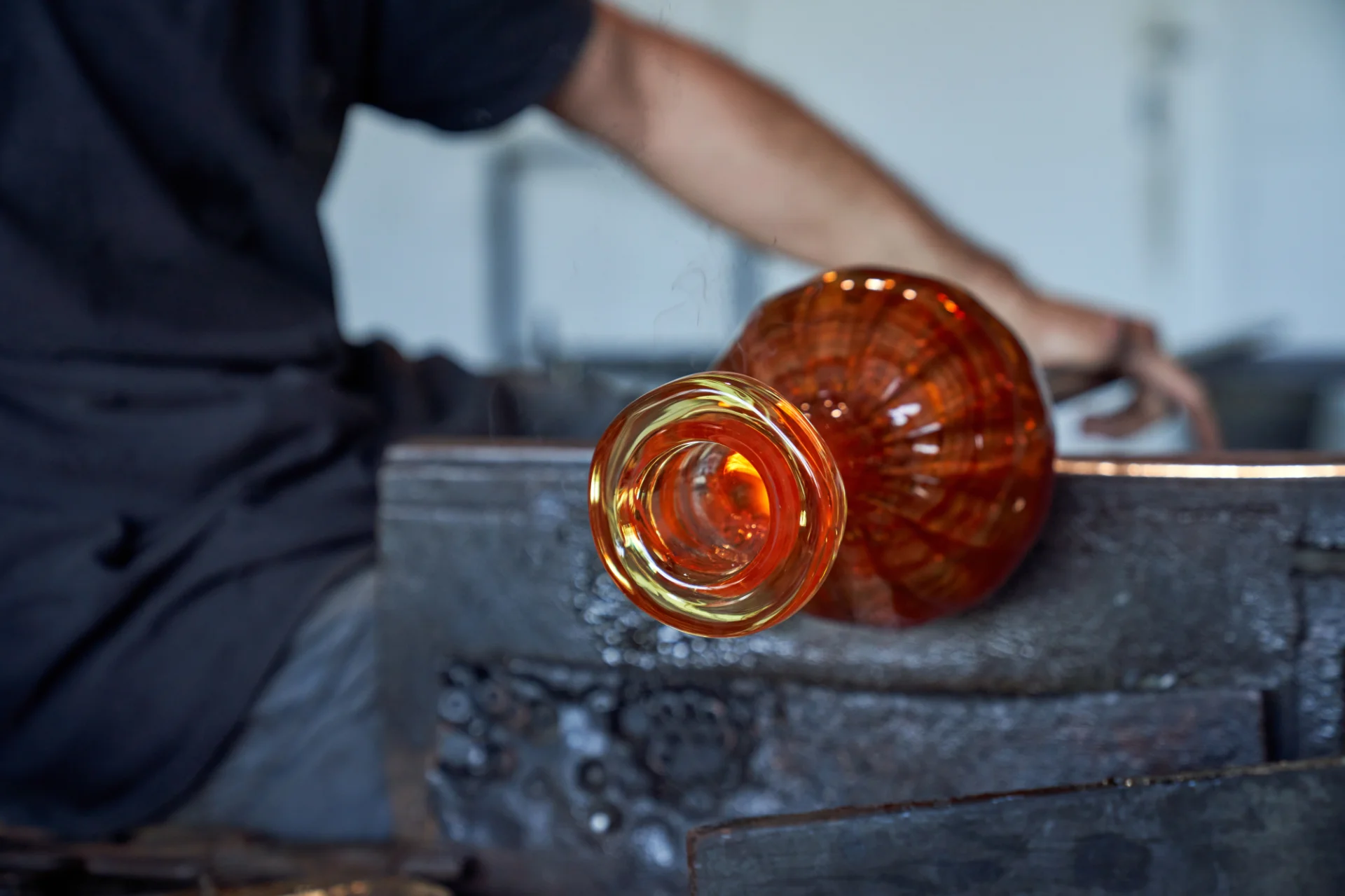
In mouth-blown glass, a glassworker supplies air through a blowpipe. In machine-blown glass, equipment controls the inflation cycle. For lighting shades and covers, compare finished samples for mounting fit, local wall thickness and appearance in the installed luminaire, since the blowing method alone gives no measure of those outcomes.
What changes when the blowing step is mechanized?
A blowpipe carries the hot glass and provides a passage for air. In furnace glassblowing, the glassworker inflates the gather and can manipulate the hot form with tools, reheating or rotating it as the shape develops. In a machine-controlled process, equipment delivers air through the tooling according to a defined cycle. When an operation is described as semi-automatic, ask which steps the equipment controls and which are still performed by an operator. That description is more useful for a lighting project than a single label for the entire sequence. See the Corning Museum of Glass entry on blowing.
Air delivery and shape control are separate choices
A mouth-blown part can be free-blown or formed in a mold. In free blowing, the glassworker develops the shape through inflation and manipulation with tools. In mold blowing, the hot glass expands against a cavity that can define its outer profile and transfer a pattern. A part can therefore have an operator-controlled inflation step and a tool-defined surface. Ask about the mold separately from the source of the air, especially if the design depends on the orientation of a texture or the position of a parting line. See the Corning Museum of Glass definitions of free-blown glass and mold blowing.
What machine blowing can control
Machine blowing is well documented in container manufacture. Historical bottle machines used a neck-forming tool, an intermediate form known as a parison, and a final mold in their forming sequence. Mechanization changed which steps could be repeated as part of a machine cycle. This history explains the meaning of machine-controlled forming in a documented industry. It gives no tolerance or production-volume threshold for a lamp shade. See Miller and Sullivan's study of bottle-making mechanization.
In a lighting development review, record where the process controls the outside profile, where the part is opened or finished, and which features are checked after cooling and finishing. A repeatable air cycle can repeat an input. The finished component still reflects the glass entering that cycle, how the tooling constrains it, and what happens to the opening and surface afterward. The lighting glass forming overview introduces those process choices. If the open question is which forming family fits the part, see the comparison of pressing and blowing for lighting glass.
See hand mold blowing in production
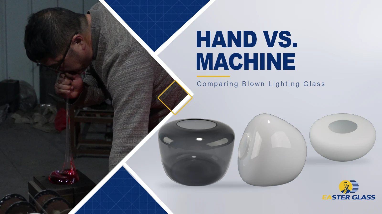
The Easter Glass process video shows an operator working with hot glass and a mold. Watch how the tool constrains the outside shape while the glassworker handles the hot part. For a drawing review, the useful follow-up is to locate the surfaces established at this step and those established later. A short production clip illustrates the operation. Dimensional and visual consistency require a separate sample record.
What does consistency mean on a lighting drawing?
Check the mounting interface independently of the silhouette
A globe can look round and still sit off center in the finished luminaire. The body profile, the opening, the seating face and the relationship between the opening and the body center are separate characteristics. A short neck can also make the transition from the glass to the holder visible, so the way the rim sits may affect both fit and appearance. The tea brown globe with a short mounting neck provides a concrete geometry example. The globe shape and the fitting end can be described and checked separately.
Define the assembly reference before comparing samples. If a retaining ring bears on the rim, identify the actual seating surface and check whether it sits evenly in the intended holder. If a clip locates the outside of the neck, use that outside surface for the fit check and keep the internal opening size as a separate requirement where needed. An overall diameter measurement serves the silhouette or clearance requirement. A fixture fit check answers how the shade seats on the mating hardware, which is a different question.
Map wall thickness by position
For wall thickness inspection for blown glass shades, mark the required locations on a section view. A globe may need readings at the neck transition, shoulder and main body, with additional positions where the shape or use warrants them. For a round part, define a repeatable orientation and angular positions when checking circumferential variation. Record which wall is measured and how the locations are reached. A reading at the opening describes that local section. An average or weight value can conceal differences in where the glass is distributed.
Local thickness depends on how the hot glass is distributed and stretched during forming. In a studied container blow-blow process, calculations were compared with measured thicknesses, and the authors examined how the initial temperature distribution of the preform affected the result. The engineering implication for a lighting review is to measure the actual profile at relevant points and treat the starting shape and thermal history as variables when investigating differences. The study concerns containers. It supplies a mechanism to consider, with lighting geometry and acceptance limits determined on the actual part. See the Eindhoven University of Technology study on blow-blow forming.
- A Neck near the opening
- B Shoulder transition
- C Sidewall
- D Crown opposite the opening
Separate forming from material and subsequent finishing
Treat a hollow outline, the starting stock and the glass composition as separate specifications. The Borosilicate Glass range of tubes, shades and covers is organized around material, so use it when the material requirement is the starting point for review. Then state the product geometry and the manufacturing steps that affect its critical surfaces. This matters when comparing a shade developed from hot glass in a cavity with one developed from glass tubing. Parts can look similar in silhouette while requiring different checks on the opening, body and finish.
Compare the condition in which the part will be delivered and assembled. A rim cut or finished after forming has its own dimensions and edge condition. Surface treatment can introduce another variable after the hollow body has taken shape. The gradient-frosted borosilicate tube shade illustrates a separate finish requirement. Its cylindrical body and its transition from frosted to clear are distinct features to check. A consistent overall length alone tells the reviewer little about where that transition sits relative to the holder.
| Feature | Mouth-blown review | Machine-blown review | Evidence on the finished part |
|---|---|---|---|
| Inflation | Document the steps the glassworker controls. | Record the air cycle and any operator-controlled steps. | Comparable samples from the stated route. |
| Outside profile | Identify free shaping or the mold-controlled regions. | Identify the profile set by the final tool. | Body outline and clearance to the holder. |
| Wall distribution | Identify the agreed check positions and how they are reached. | Keep the same measurement positions across trials. | Local readings at the defined positions. |
| Mounting opening | Confirm how the rim or neck is formed and finished. | Separate features formed in the cycle from later cuts or finishing. | Opening size, seating face and installed fit. |
| Visible surface | Record the approved texture and allowable tool impressions. | Identify repeated tooling features and any subsequent treatment. | Matched unlit and installed views. |
How should surface appearance be compared?
Set viewing zones and inspection conditions
Separate the visible face, any area screened by the hardware, and the surface that contacts the holder or gasket. A faint tool line in a masked band might matter to fit if it lies on the seating face. A line crossing a visible band may matter to appearance even if the shade sits correctly. Record the expected location and allowable appearance of a parting-line impression where relevant. A visible line can prompt a check of tooling or finishing, but its appearance by itself is insufficient to identify whether the air was delivered through a blowpipe or by a machine.
For lit appearance approval for textured glass globes, check pattern continuity and orientation on an assembled sample. A clear globe with a chevron-textured surface gives a useful example of a form whose pattern can be described separately from its profile. Agree with the production partner for textured lighting glass on which surface carries the pattern and where a transition or join may sit. If the shade can rotate after assembly, check more than one orientation or define how it will be located in the product.
Use both unlit and lit views
Review the finished glass unlit under the agreed inspection light, then in the representative assembly with the intended light source. Define the background, viewing directions and which regions will be compared. A grazing reflection can make a surface line easier to locate. An installed, illuminated sample helps show whether the same line or a local change in thickness is apparent in use. If the shade will be installed in a row, compare the approved appearance across several pieces under the same conditions as well as inspecting them one at a time.
When a line repeats at the same angular position on multiple pieces, compare that position with the tooling joint and any known finishing path. When its position changes, record the variation relative to the opening and any fixed reference on the part. These observations guide the next check. For example, a line aligned with the tool joint is worth investigating at the tool. If the line only appears in the installed view, also check where the light source or holder creates reflections before attributing it to the glass.
When the glass has a specified light-distribution task, add the appropriate optical check. For instance, a visual judgment about an illuminated shade cannot establish whether a component produces an agreed beam pattern. The Optical Glass collection for light-control components provides examples of components whose geometry or surface is specified for an optical function. Treat the optical requirement and the appearance requirement as separate acceptance items, even when both apply to the same assembly.
How can sample results support a route decision?
Use the same drawing, fixtures and inspection method
Start with a shared drawing revision and a representative holder. Compare samples at the same stage of finishing, with the same measurement locations and the same viewing conditions. Choose an instrument and contact arrangement suitable for the local geometry and access. At a curved or sloping surface, specify how the reading is taken so that a different contact position does not become an apparent difference between forming routes. Where practical, repeat selected readings before assigning the observed spread to the glass. This follows the distinction between measurement variation and process variation described in the NIST measurement process handbook.
When a manufacturer of custom blown glass shades supplies pilot parts, keep the sample identifiers with the measurement record. Link each reading to its position on the part and record the relevant trial condition where available. If there are multiple tools or stations, keep that information with the results so a shift affecting a subset of parts is visible. For repeat orders, a supplier of replacement glass globes can check the same interface against a representative holder from the intended assembly. This makes it easier to compare samples across trials and revisions.
Worked example for a globe and retaining ring
Consider a globe shade with a short neck, a visible shoulder and a retaining ring that hides part of the rim. During initial review, the samples have a similar body profile. Some nevertheless sit at an angle in the holder. Measure the relevant neck and seating features first, then compare the body position after seating. This separates a possible interface issue from variation in the outside profile. If the hardware itself varies, use the agreed representative fixture and record which holder was used rather than mixing readings from several assemblies without identification.
Now suppose the parts seat evenly but one shows a band when the light is on. Mark the band on the drawing view and compare it under the unlit and lit setups. Check whether it follows a mold joint, aligns with an intended finish transition, or corresponds to an area with different wall readings. Those observations help define the next inspection or trial. For example, an acceptable pattern at the approved orientation could still require a change if the holder leaves the shade free to turn and exposes a transition on the front. The right follow-up depends on where the difference appears and whether it affects the assembled product.
Record the approved reference and, where useful, a sample that represents the visual limit. Specify which conditions can be evaluated against that sample and which still require measurements. A visual reference can show how much line contrast a team accepts in a particular zone under a defined light. A gauge or measured limit can show whether a seating feature falls within its specified range. The Easter Glass quality page on inspection and limit samples describes the role of agreed inspection criteria in project review.
Read the spread against the requirement
For made-to-drawing glass globe prototypes, ask which of the samples represent the intended tooling, finishing and assembly conditions. Record both the individual results and the range seen in the trial. A stable-looking set can be consistently off target, and a set centered on the nominal size can still include parts that fail fit or appearance criteria. Review these outcomes by characteristic. Treat early sample results as trial evidence. Demonstrating process capability requires data from a stable process and comparison with the specified limits. See the NIST guide to process capability.
What should the project team specify before sampling?
During OEM drawing review for blown glass shades, identify the mounting references, the outside envelope, accessible wall measurement locations, edge condition and visible zones. If custom tooling for textured glass shades is being discussed, identify which regions carry a pattern and where the tool may leave a transition. Supply an assembly view or representative holder so the project team can see which regions are exposed after installation. The Easter Glass drawing and sample development route provides the project context for aligning these inputs before sample approval.
State the intent behind each requirement. An opening might need to clear a mating piece, locate the glass or seat on a gasket. Those functions can require different measurements. A finish requirement might protect visual uniformity around a pendant or define a change from a clear to a treated area. Describe what matters in the final assembly and whether there is room to move a seam, finish boundary or other visible feature. This lets the team assess forming and finishing choices without treating an existing sample’s every incidental feature as part of the specification.
When a named blowing route is part of the design brief, state whether it is a required production method or an initial preference. For a required method, document the specific operation and confirm it with the project team. For a performance-led brief, define what evidence would allow two candidate routes to be compared. A small review pack can contain a revision-controlled drawing, sample identities, measurement positions, unlit and lit reference photos, and the record of the intended mounting condition. These items give later trials a common basis for comparison.
Technical Takeaway
Use the blowing label to describe how inflation is controlled. Use the drawing and sample record to show whether the glass meets the job. Compare the mounting geometry after finishing, local wall readings at the same positions, and surface appearance under the same unlit and installed conditions. If the results differ, trace the difference to the feature, its location and the forming or finishing step that may affect it. That gives the next trial a specific question to answer.
Frequently Asked Questions
Is mouth-blown glass always free-blown?
A mouth-blown part can be shaped freehand or in a mold. In either case the glassworker supplies air through a blowpipe. In mold blowing, the mold constrains the outside form as the glass expands. Ask about both the inflation method and the use of tooling when the surface or profile is critical.
Does machine blowing give tighter tolerances on a lamp shade?
The method can repeat a defined cycle, but the tolerance achieved for a given feature needs measured evidence on that finished shade. Check the drawing requirement against comparable samples made under representative conditions. If the critical feature is a finished rim or a trimmed opening, include that operation in the review.
Can a mold seam identify the blowing method?
A parting-line impression indicates a feature worth checking against the tooling and surface specification. It can be present on an operator-blown part formed in a multi-part mold. Determine the process from the documented forming sequence and assess the line against its agreed position and appearance in the installed assembly.
What should be supplied for a blown shade drawing review?
Send the finished part drawing and the relevant holder or mounting drawing. Mark the contact face, opening, wall check locations, visible surfaces and any required pattern orientation. Add reference samples or images and describe the conditions for comparing the installed appearance. Identify any required forming method separately from the dimensional and visual requirements.
Review the Forming Route for Your Glass Shade
Share the shade drawing, mounting details and an appearance reference. Mark any critical wall thickness locations or visible seam zones so the project review can address fit, finish and the evidence needed to compare samples.
Submit Your Shade Drawing and Mounting Details
Technical note. The diagrams illustrate general forming and inspection concepts. The process video documents the operation shown. Geometry, glass grade, tooling, inspection method and acceptance criteria must be agreed for the individual project.
 English