Direct Answer
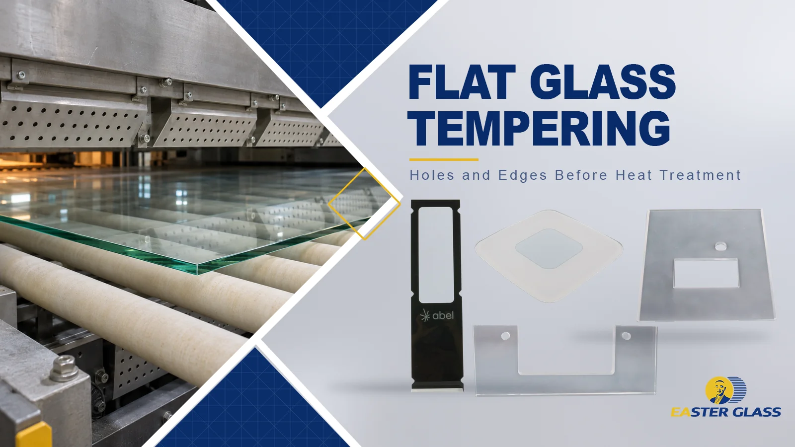
Thermal tempering reheats flat glass and cools its faces rapidly, leaving the surfaces in compression and the interior in tension. Complete the final outline, holes, notches and specified edgework before heat treatment. Check the finished cover against the drawing, the required heat-treated condition and its fit and appearance in the intended luminaire.
What changes when a flat glass cover is tempered?
Rapid cooling creates a through-thickness stress profile
The faces of a reheated plate lose heat faster than its interior during the quench. The cooler outer regions become rigid first. As the hotter interior continues to cool and contract, the regions remain joined, leaving the faces in compression and the interior in tension. The resulting stress profile is the purpose of thermal tempering. See the Lehigh University lecture on annealing and tempering for the principle illustrated in a flat plate.
Surface compression opposes tensile stress applied at the glass surface. The finished part still has to be assessed with its actual edge condition, geometry and support. A plate held around its perimeter can see a different load from a plate held by clips near openings. Record the intended support and where the glass can move or make contact in use. These details matter alongside the required heat-treatment condition when the luminaire is reviewed.
Annealed, heat-strengthened and fully tempered are different states
Annealing uses controlled cooling to limit residual stress from the earlier process. Heat strengthening and full thermal tempering deliberately develop compression at the surfaces. In the flat-glass framework, heat-strengthened glass has a lower level of compression than fully tempered glass. State the required condition on the drawing and identify the specification and evidence that will establish it. Where the project calls for particular breakage behavior, give that requirement and its acceptance method separately.
Put the material designation, treatment condition and required test evidence in separate fields. For example, the grade identifies the glass to be processed, and the treatment condition identifies the intended state after heating and cooling. The evidence field identifies the document, sample or test result that will support acceptance. This makes the drawing usable if a prototype is reviewed for fit before a fully qualified production part is available. Mark the sample state in that review so a geometry approval can be carried forward on its own terms.
| Condition | Processing objective | Evidence for a project |
|---|---|---|
| Annealed | Limit residual stresses from processing. | Material and part condition for the drawing or trial. |
| Heat-strengthened | Develop a controlled level of surface compression. | Specified condition and applicable verification method. |
| Fully tempered | Develop the higher-compression state under the applicable specification. | Specified condition plus any applicable breakage or assembly checks. |
Why finish holes and edges before tempering?
Complete the glass-removal operations
Cut the blank to its specified profile, form the openings and notches, and complete the required edge and surface fabrication before the heat-treatment stage. The hole boundary is itself an edge and belongs in the edgework callout. An internal corner, a through hole and a stepped seat may each have a different finishing requirement. The National Glass Association guidance on fabrication before heat treatment describes the effect that subsequent machining can have on heat-treated glass.
The final stress state depends on the surfaces and edges present when the part is heat-treated. Removing material from a tempered component can disturb that state or cause the glass to break. If a revision moves a hole, enlarges a notch or changes the finished outer size, revise the blank drawing and run the appropriate sequence again. Keep the old and revised sample records distinct so the approval follows the actual geometry that went through heat treatment.
For an edge that will be visible, the drawing can define both the edge profile and its appearance. For an edge that will seat inside a frame, include the bearing face and the clearance it needs. Give the edge treatment for the hole or cutout as well as the outer perimeter when both matter. Mark where an edge condition changes so the person checking the part can identify which requirement applies to each region.
An edge can be prepared with its sharp corners broken, ground to a defined face or finished to an agreed polished appearance. Select the requirement for the function of that edge. For example, a frame can cover a prepared edge while leaving its profile important to fit. An exposed edge can need both a finished profile and an appearance reference. Surface operations that remove glass also belong in the pre-treatment fabrication review. For printing or coatings, confirm the approved sequence for the chosen material and finish system.
Check the material that remains around an opening
Hole diameter and position describe the clearance at the opening. The remaining glass between the opening and the nearest edge is a separate feature. Check that remaining width in the region where the two boundaries come closest. A notch beside a hole or a change in the edge contour can move that location away from the obvious dimension line. Provide a plan view that shows the relationship and a section where the thickness or edge shape changes.
For a flat panel with an inner corner, specify the corner radius and identify any nearby mounting or clearance surface. For a stepped rim, give the transition and remaining section where the step runs close to the opening. Review the actual glass, thickness and geometry together before fixing the design. The qualified route for a rectangular blank provides useful context for that part. A new hole pattern or a narrow region calls for its own review.
Review the minimum remaining section in the same model used to approve the mating part. A bevel can leave less material near one face than a top view suggests. A slot can have its narrowest bridge at a rounded end because the perimeter changes direction nearby. Draw the section through the limiting point and identify the face on which the size is measured. If the layout moves a hole or changes the thickness, revisit the affected edge and supporting surfaces together before starting the revised blank.
The stress that a thermal treatment develops depends on the glass, its thickness and the cooling conditions. Thin sections can lose heat through their full thickness quickly, which makes it harder to develop the temperature difference needed for the required surface compression. Steps and uneven sections also make uniform cooling harder. Review the narrowest section, its edge profile and the specified glass condition together. Use process and sample evidence for that combination when setting a limit for the drawing.
| Feature | Show on the drawing | Check on the finished part |
|---|---|---|
| Perimeter | Outline, datum and installation orientation. | Clearance and location in the actual frame. |
| Hole or slot | Size, position and the remaining glass at its closest edge. | Clearance through thickness and location relative to the seat. |
| Notch | Depth, transition radius and nearby edge detail. | Interference at the corner and around the mating feature. |
| Finished edge or step | Section, bearing face and finish by region. | Edge profile, contact and seated height. |
| Printed or coated area | Artwork or coating boundary, viewed face and project sequence. | Alignment and appearance in the specified viewing setup. |
See a glass cold-working operation
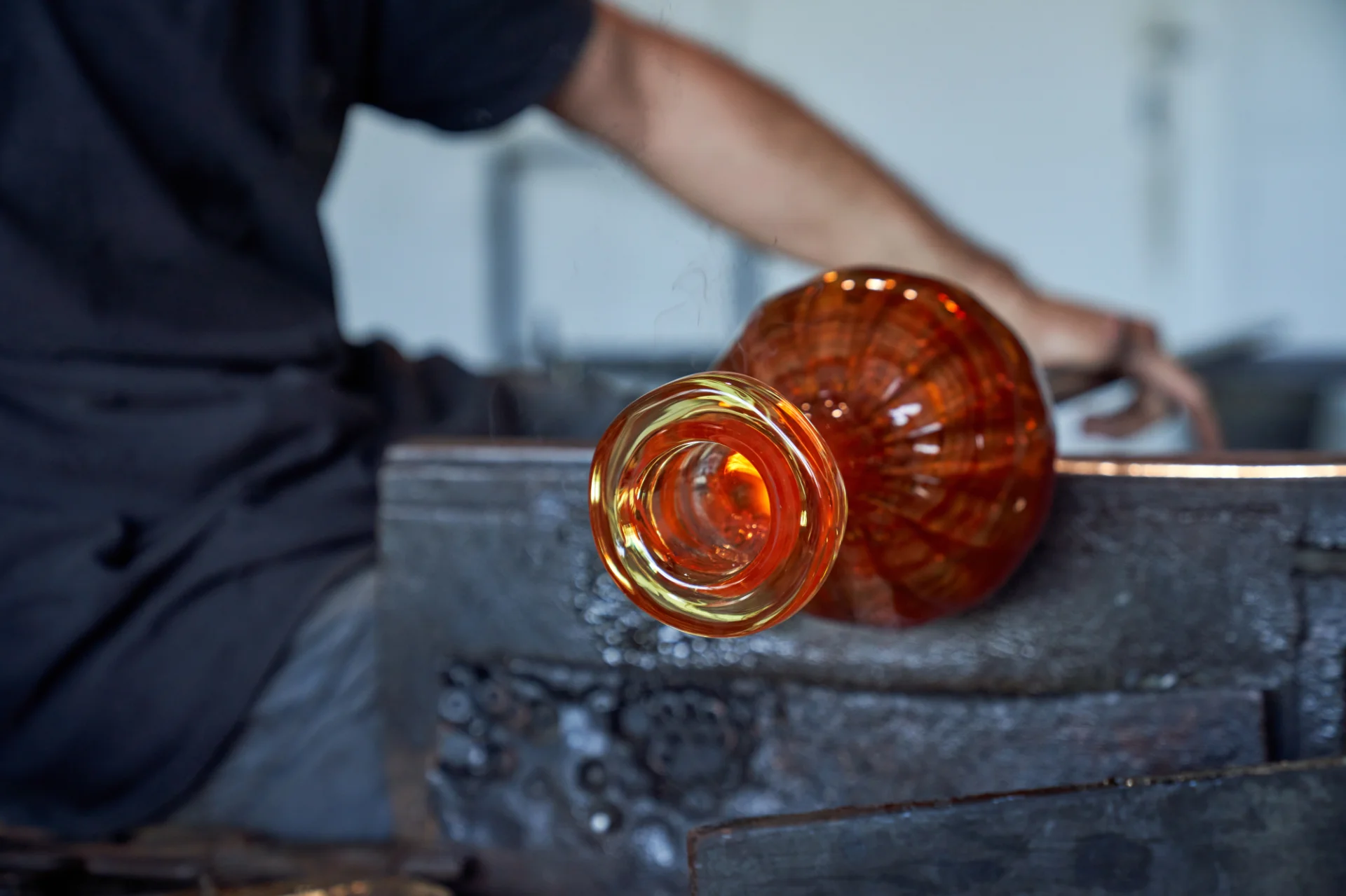
The Easter Glass production clip shows cold working on a formed borosilicate component. It illustrates secondary fabrication that removes glass to change the finished geometry. For a flat cover, the drawing defines the openings, edge geometry and fabrication that precedes thermal treatment.
How do three flat parts change the drawing review?
Irregular contour in a locating frame
The published irregular printed PYREX panel with an angled contour is listed under flat glass tempering. Its contour gives the review team several places to check fit. With a manufacturer of irregular tempered borosilicate panels for recessed luminaire frames, identify which portion of the outline locates the panel and which portions provide clearance. Specify the corner transitions and record where the finished outline is inspected relative to the mounting reference.
An irregular panel can fit one way round and sit differently when rotated. Give the viewing or installation orientation on the drawing and use it when checking the outline. If the fixture locates the glass at two distinct edges, record the relative position of the critical angled feature with respect to those edges. This makes it possible to compare the finished part and the frame against the same reference, including any final edgework on the locating faces.
A profile gauge or digital comparison needs a defined alignment. A comparison that floats the glass outline to its nearest position can make a locating error hard to see. Locate the sample using the specified references, then compare the clearance contour where the panel passes the frame. If the fixture has left and right variants, state the intended variant and viewed face in the approval record. This helps keep an orientation issue separate from a change in the machined shape.
Printed flat cover in a lit opening
The compact printed PYREX flat glass panel is a separate published example with a visible graphic and a listed flat glass tempering process. When reviewing samples from a supplier of printed tempered glass covers for backlit luminaire openings, specify which face carries the graphic, the intended viewing direction and its position after installation. Establish the transparent area and the boundary where the print may meet a mask, trim or gasket.
The material designation and the required heat-treated state are separate entries on the drawing. The Easter Glass Borosilicate Glass collection for material-specific cover examples gives context for other components made from that glass family. For the printed panel itself, agree the material, print system and sequence for the project. Approve graphic position and lit appearance on a sample with the final finish in the intended holder. The print layout should use the same locating references as the finished part when those positions affect the visible aperture.
A printed mark viewed through the glass needs the artwork orientation defined from the observer’s side. A printed border can align with the mask in a straight-on view and show a visible shift at an angle if the two surfaces are separated. Record the intended view and assemble the cover at its working spacing when that appearance matters. Retain the approved artwork and viewing setup with the sample record so a later change to glass thickness or the holder can be reviewed consistently.
Stepped disc with a central opening
The stepped ultra-clear glass disc with a central opening combines an outer stepped profile with a round opening. Its published data also lists flat glass tempering. In a drawing review with a factory tempering stepped glass discs with central clearance openings, specify which feature centers the disc in the assembly. Give the relevant centerline, step height, seating face and relationship between the opening and the outer profile.
If a projecting component passes through the hole, show its envelope and the clearance needed through the whole thickness. The minimum clearance can occur at one face of the hole or at the step, depending on the mating shape. Use a section drawing to show the relationship and check both the hole edge and the annular seat. A central opening that provides clearance and an outer step that carries the disc are two different functions. A sample can be measured and assembled to confirm each function in the intended orientation.
What should the finished glass and assembly checks show?
Separate free-state measurements from fixture fit
Define how the glass is supported while its outline, flatness or step height is checked. Then record the support and retention conditions in the luminaire itself. A panel can measure correctly in a free-state setup and still contact a frame where the assembly has less clearance. A complete first-article record identifies the glass revision, mating frame and any gasket or retaining part used during the trial. For project inspection and approval-sample context, see Easter Glass quality control and inspection.
If flatness affects the assembly, define the measurement region and the support setup before comparing results. Overall bow and local variation over a short seating region can have different effects on the same cover. A long-span check may describe the panel shape while a check at the gasket line addresses the actual contact. Give the locations and conditions relevant to the fixture drawing. When a panel has a printed or coated face, record its orientation so the glass and the appearance can be compared consistently.
Consider a flat cover that drops into a frame with its clips open but rocks when they close. First locate the intended bearing surfaces and check whether the glass is seated at each one. Compare the free-state glass shape and the frame opening against the drawing. Then observe where the clips and gasket contact the assembled cover. An unintended contact at a corner can affect the seated height at the opposite side. Record which surfaces were actually carrying the part during the fit trial.
If the trial points to an interference, record whether the frame, glass profile or edge condition requires a change. Confirm the revised clearance with the same reference features and the intended hardware. For a changed glass contour, the next sample comes from a revised blank and its own heat-treatment record. This is one reason to perform a drawing and fit review before releasing the finished part for repeat production.
Check appearance and heat-treatment evidence separately
A strain pattern in heat-treated glass can become visible under certain lighting conditions. Set the viewing direction, illumination and background used for appearance approval. If a flat pane sits ahead of a shaped lens, the pane and lens have separate geometry and appearance criteria in the assembly. The Easter Glass Optical Glass collection for lens profiles gives examples of shaped optical components. The final lit check should use the intended pane, lens and light source when all are part of the design.
When the glass specification calls for a stress measurement, use a method appropriate to the glass and sample configuration. ASTM C1279-23 on photoelastic edge and surface stress measurement describes a non-destructive method for applicable light-transmitting flat glass. Confirm the measurement face, edge access and instrument suitability. Under this method, surface stress on float glass is measured on the tin side. Keep the measured region and sample identification with the result. A visual strain pattern is an appearance observation. A measured stress and a specified breakage result each need their own evidence.
Match the qualification evidence to the component and the luminaire
The NGA Engineering Standards Manual includes a glass specification for fully tempered soda-lime parts in applications such as lighting fixtures. Its material and use scope matters when specifying an individual component. At the equipment level, IEC 60598-1 general requirements and tests for luminaires addresses the luminaire. Determine the applicable edition and product requirements for the project, then document the glass evidence and assembly evidence at their respective levels.
For made-to-drawing tempered glass covers, use the same part revision to coordinate outline, edge profile and acceptance state. In an OEM drawing review for perforated flat glass panels, give the required glass condition and supply the mounting section. For custom tempered glass disc prototypes, include the component that passes through the opening when it determines clearance. These inputs help the review team identify which dimensions to verify on the finished glass and which checks to perform with the actual assembly.
Technical Takeaway
Finish the outline, openings and edges before thermal treatment. Define the required glass state and the evidence for it, then use the actual frame and hardware to check the finished cover. A change to the machined geometry goes back to the blank drawing and a new production and approval record.
Frequently Asked Questions
What is thermal tempering of flat glass?
It is a heat treatment that reheats glass and cools the faces rapidly to produce compression at the surfaces and balancing tension inside. The process is qualified for a defined glass and geometry.
How does heat-strengthened glass differ from fully tempered glass?
Both have surface compression from heat treatment. Heat-strengthened glass is the lower-compression condition in the applicable flat-glass specification. Specify the required glass state and any breakage or application test separately.
When should holes and notches be made?
Machine the openings and complete the specified edgework before the heat-treatment stage. If the finished design needs an opening change, make the revised blank and verify the new part after treatment.
How can the required temper level be checked?
Agree the glass specification and the appropriate verification method. An applicable photoelastic method can measure stress at selected surfaces or edges of flat glass. Record the measurement locations and sample condition with the result.
Review Your Tempered Flat Glass Drawing
Share the flat glass drawing, mounting section and required heat-treatment condition. Include the final hole and edge details, intended viewing conditions and any acceptance tests so the glass and assembly checks can be defined together.
Share Your Flat Glass Drawing and Fixture Details
Technical note. The diagrams explain process and design principles. Published examples support their stated geometry and process labels. Grade, geometry, treatment condition and fixture performance are confirmed for the particular project.
 English