
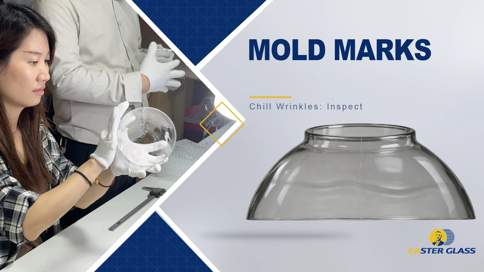
# Glass Mold Marks and Chill Wrinkles: How to Identify and Inspect Them
Start with an observation, not a defect verdict
A line near a glass lens edge might be a tool-joint trace, intended transition, shallow ridge, finishing mark, or crack-like feature. A wavy patch may reflect formed geometry or a thermal-contact feature. Record what is visible before naming a cause.
Record the drawing revision, viewed face, location from a datum, and whether the feature repeats. State the light source and viewing direction. Use a photo only when the setup and orientation are repeatable.
This article focuses on classifying formed surface observations. It is not a general defect survey, an annealing guide, or an instrument tutorial. The lighting-glass defect overview maps the broader defect families; the pressing process guide for lighting lenses and prisms covers forming. Here, the question is what evidence is needed before a line or ripple is accepted, rejected, or assigned a cause.
Three terms that should not be collapsed
Mold mark is a broad visual description
“Mold mark” is an informal label for different observations: a tool-split line, contact imprint, transferred texture, or later-visible feature. It does not identify a process stage or prove the mold caused it.
A line repeated in the same position may match a tool split or contact boundary, making the tool a reasonable lead. It is not proof: a fixture, transfer point, or finishing operation may share that location. Compare stages and records before assigning a cause.
A mold can create intended geometry: a raised pattern, Fresnel step, or perimeter flange may be part of the drawing. The question is whether the surface matches the specified form and location. A textured part can still have a separate crease, flattened area, scratch, or crack.
Chill mark or chill wrinkle describes a wrinkled surface condition
Corning’s public glass terminology note describes a chill mark as a wrinkled glassware surface associated with uneven mold contact. ASTM C162-23 is the current ASTM standard titled Standard Terminology of Glass and Glass Products. These are terminology references, not universal acceptance limits for custom lighting parts.
Treat “chill wrinkle” as a visual descriptor until geometry and process evidence are checked. Record whether it is a broad ripple, narrow crease, or local waviness and locate it from the drawing. Appearance alone cannot identify a process setting.
Usage can vary by factory, product family, or translation. If a specification uses the term, define it with a location, image, and acceptance rule. Otherwise, record the visible feature first—for example, “shallow wavy trace on the outer wall, below the rim”—and list the suspected cause separately.
Chill check is a crack-like flaw, not simply a ripple
A chill check is not a synonym for a cosmetic chill mark. NIST’s *Fractography of Ceramics and Glasses, Third Edition* describes small, tight thermal cracks that can form when hot glass has very localized contact with a cooler object. The cracks may be difficult to see and can matter to later fracture analysis.
If a feature may be a crack, do not classify it from one photo. Preserve the part and orientation, avoid rubbing or polishing the area, and arrange a project-appropriate technical review. If it has fractured, retain the fracture surfaces for specialist examination.
A record should distinguish “surface ripple,” “tool-parting trace,” and “suspected crack.” If the inspector cannot tell whether a feature is open or reflective, state that uncertainty instead of assigning an unsupported name.
Why appearance alone is weak evidence
Transparent, reflective, curved glass can change appearance as the part or light moves. A ridge may appear bright in reflected light and disappear in transmission; a tight crack may reflect only at a certain angle. A designed pattern can also resemble a ripple when viewed obliquely.
“Visible” is not a complete inspection condition. Record source position, viewing direction, part orientation, and whether the component is alone or assembled. Keep appearance, profile, fit, optical, and stress checks separate unless the project plan combines them.
A line can have a sharp edge, smooth transition, raised relief, or shallow valley; these distinctions matter when the drawing controls a profile. If the requirement is purely visual, a height measurement may not add useful evidence. If the feature could affect seating or an optical face, a photograph alone is insufficient. Choose the check that addresses the stated requirement and use images to document location and viewing condition.
A review of precision glass molding describes mold–glass interface effects such as adhesion, waviness, and surface irregularities in optical molding systems. That literature is useful for understanding why contact and release can matter in that process family, but its examples involve precision-molded optical materials and tools. It should not be used to infer the cause, severity, or process window for hand-blown lamp shades or ordinary pressed lighting parts. The specific glass, forming route, tooling, and inspection stage matter.
Diagnosis should combine morphology, part location, and repetition across samples or stages. When evidence is incomplete, label the cause provisional—especially near a seating, sealing, optical, or retaining zone.
A practical inspection sequence
1. Register the part and the viewing condition
Use a stable orientation based on a drawing datum, opening, edge, or mounting feature. For a globe or tube, a clock position can work if its zero is tied to a reference; for a lens, use the drawing orientation.
Record the part or sample ID, drawing revision, process state, inspection date, and lot where available. Separate as-formed, finished, coated, and assembled states if the surface can change between them.
2. View the feature under repeatable lighting
Use the specified viewing condition. If none exists, record repeatable reflected and, where possible, transmitted views. Rotate the part or light through several angles when checking for a possible tight crack; this search is not a calibrated acceptance test.
Directional light can reveal relief because a small slope change moves the highlight, but it can also exaggerate normal contours or texture. Use the same source and part orientation when comparing an approved reference; define which viewing condition controls disposition.
For a lens or diffuser, separately check whether the feature changes the intended appearance or light behavior in the fixture. Compare it with the optical drawing, approved sample, or fixture requirement rather than a generic expectation of a smooth face.
3. Map the feature against the intended geometry
Compare the line or ripple with the drawing: does it follow a split, rib, step, flange, rim, or opening? Does it interrupt the intended pattern or enter a mounting or sealing area? This helps separate design geometry from a new anomaly.
A repeated pattern may be the intended design. The frosted borosilicate Fresnel lens with concentric steps and low-profile rim and clear grid-pattern borosilicate lens with raised face relief and seating rim show listed geometry, not known defects. Likewise, the clear flanged borosilicate glass dome cover with a formed perimeter flange illustrates an interface feature. For a custom part, mark the intended visible field and mounting zone on its drawing.
4. Compare locations across parts and stages
Mark the feature on a drawing outline and compare several parts in the same orientation. A consistent position can lead to a tool review; variation may point elsewhere. Check the location against the intended pattern, split, mounting surface, and visible zone.
Compare pre- and post-operation samples under the same viewing condition, and record the stage, face, and orientation. This is stronger than comparing photos made with different light or background. If no earlier sample exists, state that the stage of origin is unconfirmed.
A highlight can reveal relief and can also exaggerate normal contours.
Use when the part and requirement allow a view through the glass.
Register the feature to a datum before comparing samples.
| Observation | What it can suggest | What it does not prove | Useful next check |
|---|---|---|---|
| Line repeats at a consistent location | A shared tool, split, fixture, or handling contact may be relevant | That the mold alone caused it, or that every repeated trace is rejectable | Compare location with tooling and assembly features; check samples at earlier and later stages |
| Broad wavy patch on a formed surface | A surface-form or local cooling/contact hypothesis may be worth testing | A specific temperature, dwell time, or cooling fault | Map its boundary, check the profile if required, and review forming records with the process owner |
| Feature follows an intended rib, step, or texture | The mark may belong to the designed geometry | That the feature is within profile or optical requirements | Compare with the drawing, approved sample, and relevant functional check |
| Short, tight feature with a crack-like reflection | A crack-like flaw, including a possible chill check, needs technical review | The origin, depth, or remaining strength of the part | Preserve the part and orientation; use an appropriate expert examination or project method |
| Feature appears only after assembly | A contact, clamp, gasket, or viewing-path effect may be involved | That the glass left production in that state | Compare free and assembled states; check support points, clearances, and handling records |
Table 1. Use visible observations to select the next evidence step; do not treat the observation as a confirmed cause.
Investigate a recurring feature without changing the wrong process
Corrective action should follow evidence. Changing tool temperature, cooling, pressure, release, or handling because a line was called a chill wrinkle may affect another feature. No single setting applies to every glass, shape, tool, and forming route; process changes require the relevant records and owner review.
List competing explanations before choosing a cause: the line may follow a tool split, a transfer contact, or an intentional rib reflection. For each, write what evidence would support or weaken the hypothesis.
Check whether the feature repeats across different tools, cavities, lots, or finishing routes. Compare the observation with available tooling drawings, release direction, handling path, and secondary operations. Preserve the sample and its process identity if a tool contact is suspected.
A recent review of precision glass molding links mold–glass adhesion and contact conditions with surface irregularities in that specialized optical process. It is useful context, not a recipe for another route. Do not infer Easter Glass mold materials, coatings, settings, release agents, or tool-life limits from this literature.
Record the feature ID, drawing revision, face and datum location, viewing condition, sample and lot IDs, process stage, comparison images, candidate causes, supporting evidence, next check, disposition, and review owner.
Correlate a suspected cause only when the repeat pattern and process records agree. A recurring trace at one tool location combined with registered samples before and after forming is stronger evidence than one isolated photograph. If a corrective action is tried, record the before-and-after condition and any side effects. Keep confirmation of a cause separate from the acceptance decision: a feature disappearing does not automatically prove every functional requirement is met, and an unchanged appearance does not rule out a cause if the inspection method was not suited to it.
Example A: a line that follows the parting region
A pressed lens shows a narrow line near its perimeter on several samples. Locate it against the seating rim and orientation feature. If it matches a tool split, inspect the tool and compare another cavity or stage; do not assume it is acceptable. Then check whether it changes the required profile, seating, or light behavior against the project limit.
If the trace appears before finishing, compare forming-stage samples with later parts. If it appears after finishing or assembly, include those steps. Without earlier samples, record the origin as undetermined. The drawing can identify the visible zone, any permitted trace location, and the controlling profile or fit check.
Example B: a ripple that is called a chill wrinkle
A curved shade shows a shallow wavy patch under a narrow light source. Record its face and location, then repeat the view on other samples using the same source and orientation. Compare the patch with the designed smooth and textured zones. If contour matters, use an agreed profile check; if appearance controls, use a defined viewing condition and reference. Only then assess whether contact or cooling is a plausible cause.
Keep “chill” as a hypothesis until supported. A ripple is not automatically a crack or harmless; evaluate its effect on appearance, geometry, fit, light behavior, and stated requirements.
Example C: a short feature that reflects like a crack
A short curved line produces a momentary reflection as the part is rotated. Treat it as a suspected crack-like feature, retain the sample, and record the orientation and light movement. Request the examination specified for the project rather than grouping it with a broad ripple.
NIST explains a possible crack mechanism; it does not set acceptance for a lighting component. Use the method and criteria in the project specification. If a part has fractured, preserve the pieces and fracture surfaces for review.
Define acceptance in the drawing and inspection plan
A single visual limit cannot cover every mold trace, chill mark, texture, or lighting application. Critical zones differ between a visible globe, a functional lens, and a feature hidden behind a frame. Limits depend on the approved design, viewing condition, assembly, and project requirements.
An acceptance rule names the feature and zone, viewing condition, comparison reference, and decision rule. If size or profile matters, specify how it is measured. For assembled appearance, identify the representative fixture, source, and orientation.
| Requirement area | What the drawing or control plan should identify | Example evidence |
|---|---|---|
| Surface zone | Visible field, hidden area, patterned region, rim, seal, or seating face | Marked drawing or section with named zones |
| Feature description | Seam trace, chill-mark-like ripple, intentional texture, suspected crack, or other observable condition | Approved photo or limit sample with a short definition |
| Viewing condition | Reflected or transmitted light, part orientation, source position, assembly state | Repeatable work instruction or project inspection record |
| Geometry | Whether the feature changes a profile, seating surface, opening, or clearance | Drawing callout and agreed measurement method |
| Functional effect | Whether a light-distribution, fit, sealing, or operating check is needed | Component or fixture check against the project requirement |
| Decision rule | Location, extent, appearance, count, or profile criteria where relevant | Approved acceptance criteria, not an assumed industry-wide number |
Table 2. Tie each limit to the function and inspection condition that make it meaningful.
optical field
If the drawing or sample does not cover the feature, clarify the requirement before disposition. Propose a repeatable visual or measured rule, define the zone, and agree it before repeat production. Add a functional check when the part’s role depends on it.
The lighting glass quality and inspection overview states that inspection scope and acceptance limits are agreed for the order. Its pressed and hand-blown glass priorities include tooling features and seams, rims and edges, visual defects, and fit. Use the public page as company context; it does not prove that a particular product uses a specific instrument, receives 100% inspection, or has a particular limit.
Easter Glass context and evidence boundary
Easter Glass lists formed component families in its hand-blown glass collection of shades, globes, tubes and hollow forms and borosilicate glass collection of lenses, domes and lighting covers. These pages show product families; they do not mean every listed item is mold formed or shares one inspection plan.
For a project-specific review, the custom pressed lighting glass man ufacturer's assessment of a recurring chill mark should use the drawing revision, representative sample, part orientation, and acceptance question relevant to the fixture. A lighting glass supplier's assessment of repeated tool traces near a patterned lens should compare intended geometry with the observed location, not rely on an unregistered photo. Neither link claims a defect has been measured on a listed product.
For development work, an OEM glass lamp shade manufacturer inspection plan for patterned glass lighting surfaces can connect the drawing, sample, visible zone, process stage, and agreed criteria. Confirm any special instrument, quantified limit, or report in the project specification.
The official Easter Glass pressing clip shows glass preparation, loading, and pressing. It locates the tool-contacting operation in the sequence; it does not show a confirmed defect or prove its cause. Decide conformity from the drawing, sample, and project inspection record.
Technical Takeaway
Call the feature what you can observe, locate it against the drawing, and repeat the observation under controlled conditions. Separate an intended tool-replicated pattern, a parting or contact trace, a wrinkled chill-mark-like surface, and a suspected crack-like chill check. Compare samples and process stages before naming a root cause. Set acceptance from the actual visual, profile, fit, and functional requirements—not from an assumed universal limit.
Frequently Asked Questions
Is a mold mark always a defect?
No. The term may describe an expected parting trace, intended texture, or unwanted feature. Compare it with the drawing, approved sample, location, and function; forming origin alone does not make it acceptable or rejectable.
Is a chill wrinkle the same as a chill check?
No. A chill wrinkle is a wrinkled surface observation; a chill check is a small crack associated with localized thermal contact. Review a crack-like feature separately from an appearance ripple.
Can a photograph prove that a mark came from the mold?
No. A controlled photo documents location and appearance, not root cause. Compare parts, stages, tools, and records before assigning a cause.
How should a lighting-glass supplier inspect a suspected mold mark?
Register the part to a datum, record the face and location, and compare it under the specified viewing condition with the approved reference. Check fit or geometry when required; preserve any suspected crack for technical review.
Is there a universal acceptable size for chill marks on lighting glass?
No universal allowance is established by the cited sources for every custom part. Define limits for the product’s zones, function, viewing condition, and project requirements.
Review a formed glass surface requirement
Share the drawing or sample reference, the location of the observed feature, the process state, and the viewing condition that matters in the fixture. Easter Glass can review the intended surface, mounting geometry, and inspection question against the project’s agreed requirements.
Easter Glass supports custom lighting-glass projects with coordinated development, production, quality control, packaging, and repeat-supply service for B2B customers.
Technical note. The diagrams in this article are schematic. External references define terminology or describe mechanisms within their stated scope; they do not establish an Easter Glass process setting, product defect, inspection instrument, or acceptance limit. Confirm material, geometry, viewing condition, process stage, method, and acceptance criteria for the specific component and application.

Custom lighting glass components for OEM and ODM projects.
 English